Electrosense Assisted Robotic Manipulation
December 8, 2017
Overview
- Throughout the project, I accomplished the following:
- Built prototype electric field sensing circuits from existing designs
- Implemented target object localization with a HDT Adroit-M Undersea Manipulator robot arm with IR range finder sensing
- Human in the loop experiments with IR time-of-flight range finder
- Also setup the configuration files necessary for MoveIt!
- MoveIt! is an open source motion planning/path planning framework integrated with ROS)
- I include some videos of simulations (through RViz visualization software)
- This could be useful eventually for motion planning, such as more complex path planning if needed
- In parallel, I conducted a variety of experiments for debugging and troubleshooting the electric field sensing (currently does not work integrated into the robot arm)
- Project Advisors:
- Professor Malcolm MacIver
- Professor Michael Peshkin
- Dr. Jarvis Schultz
- Code Disclaimer:
- Some of the code base, such as those relating to the proprietary lower level control and drivers for the HDT robot arm, is not open-source. Please message for further inquiries about the code base.
Results
This section details the results of the experiments mentioned in the overview. They are presented in chronological order:
Demodulation Circuits
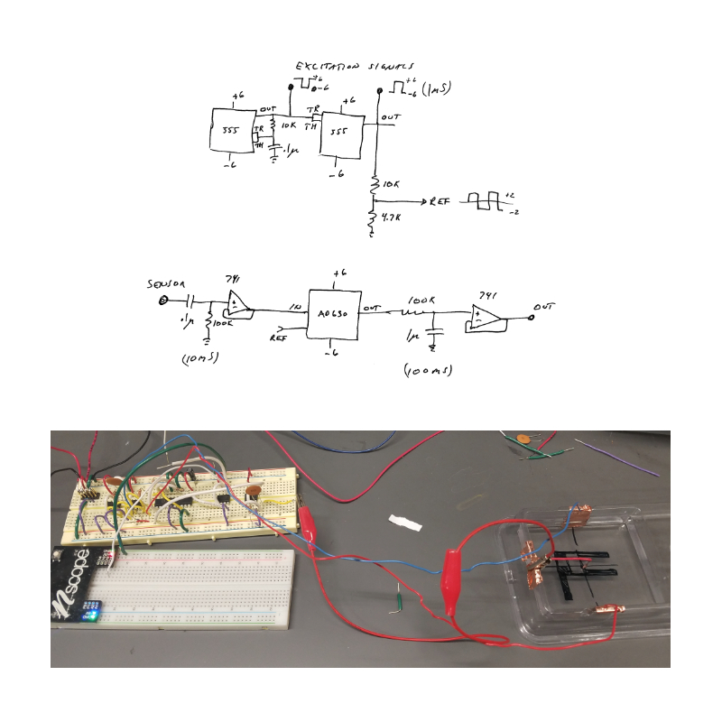
- These were built for two reasons:
- For myself, to understand fundamentally how electrosense data was collected and processed
- To set up a test bed for additional electrosense experiments such as long range electrosense (where excitation electrode and sensing electrode separation distances are relatively large)
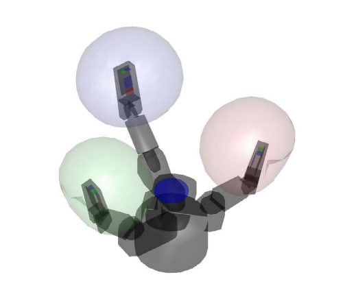
MoveIt! Simulations
- The ROS package I created to integrate the HDT robot arm with MoveIt! enables the user to specify an arbitrary start point and end point.
- The path planning problem is solved then executed in simulation
- The robot starting configuration is when all joint angles: 1,2,3 are all 0.
- The robot highlighted in orange represents the goal pose.
Object Localization
- Due to the electric field sensors not working when integrated with the robot manipulator, possibly due to unintended electrical grounding effects, I used a range finder sensor as a proxy to continue the object localization experiments.
- Range finding sensor used is a VL6180 time-of-flight IR range finding sensor, with a max sensed distance of 10 cm (manufacturer specifies >10cm can be detected, depending on object reflectivity and ambient conditions)
- Sensor data is processed on an Arduino Uno R3 Microcontroller then transferred through serial communication to ROS
- The robot end effector simultaneously scans the local environment and collects proximity distance data to find regions of interest in order to constrain the search space
- The regions of interest are those which the range sensor value (proximity distance) are smaller than average. With this, we can infer an object is nearby.
-
The aforementioned process is best described as a heuristic algorithm, with pseudocode below:
- Radial Sweeping Heuristic Algorithm Pseudocode
(1) Initialize ranges for angle sweeps [a], and sensed object tolerance threshold [b] (2) Sweep along joint 1 when joints 2 and 3 are fixed at 0; store every range sensor distance value i. Find angle associated with minimum distance value ii. Set joint 1 angle to be that angle for subsequent scans (3) Repeat for the other 2 joints (4) Terminates when joint_1, joint_2, joint_3 angle are all defined with respect to a minimum distance (5) Execute Grasp Maneuver [c] [a] joint angle limits, angle resolution [b] if detected value less than or equal to threshold, do not move joint [c] just moving every digit closer while preserving minimum distance criterion - Following the pseudocode, we can set up the object localization experiment with the following assumptions:
- A human teleoperator controls the robot joint states, with feedback solely from the returned range sensor values (human operator cannot see where real robot arm is relative to target object)
- The target object is static, and placed in a position that can be detected by the range sensor when the robot arm does a full sweep (fully covering the angles spanned by the joint limits) on one joint, while the other two joints are fixed at 0. This applies as well to the remaining combinations of angles.
- Please see the following videos:
- The robot simulation seen on the left hand side moves faster than the real robot on the right hand side because the real robot has joint velocity limits
- The videos show a side by side comparison of simulated robot visualization (with a trail showing the approximate position of the end-effector over time) and the real robot arm executing the path.
-
The videos also show a real-time printout of the range sensor values in the terminal on the left, which changes depending where the end-effector is relative to the sensed object
- The ROS nodes are structured as follows:
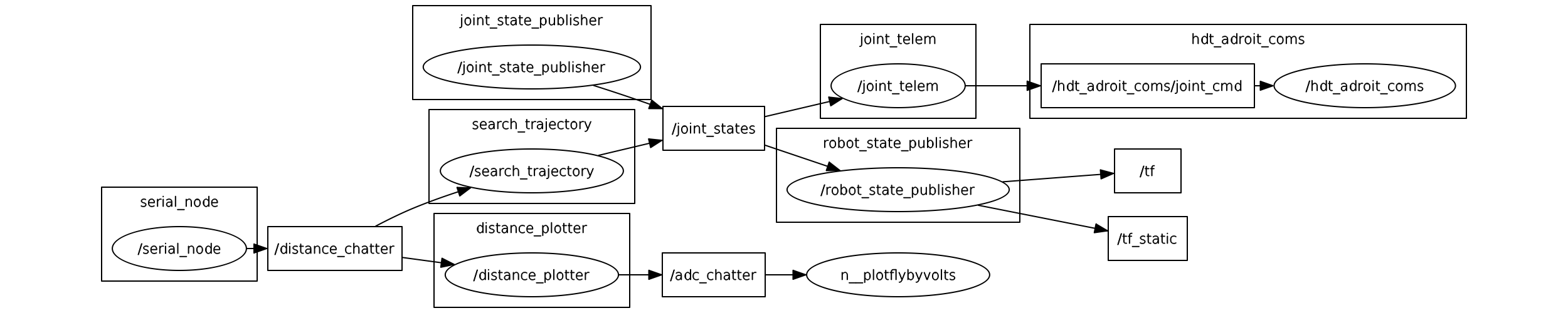
- The robot is controlled by publishing JointState commands to the joint_state topic, and ROS retrieves the range sensor output from via serial communication from the rosserial package
Human in the Loop Analysis
- The two videos show initial promise for this approach
- Trial 1:
- End effector has roughly not changed position
- It did, however, change orientation to align with the target object
- Trial 2:
- End effector changed position more than trial 1
- End effector also matched orientation of target object fairly well
- Trial 1:
- This heuristic is a “brute force” approach; a more intelligent algorithm would reduce search time
- Run time is also specified by joint angle sweep resolution (how finely the desired change in angle is in the path)
- The constraints set by the position of the target object are in place since the range sensor returns a 1D distance value (normal to the plane of the sensor board)
- If this were the electric field sensing, distance information in additional dimensions could be captured due to electric field propagation via dipole effects
- This relaxes the constraints on the target object location
- With the previous reasoning, the implemented heuristic algorithm could perform better in the search task once the integrated electrosense in robot arm is working
- With additional sensors on the digits, the additional information can be useful for a more informed grasping method
Future Directions
Continue Investigation of Electrosense and Robot Integration Issues
- further debugging steps
- Via Oscilloscope and Multimeter Analysis, probe the sensor boards in the box, focus on inspecting the raw signal passed into the box after buffer amplification. From this sequentially assess if each checkpoint gives a result as expected from understanding of the electronics (ex. demodulation)
- Find out what is grounding, or interfering with the electric field sensing
- Via Oscilloscope and Multimeter Analysis, probe the sensor boards in the box, focus on inspecting the raw signal passed into the box after buffer amplification. From this sequentially assess if each checkpoint gives a result as expected from understanding of the electronics (ex. demodulation)
Reliable Inverse Kinematics Solutions
- constrained inverse kinematics considerations for path planning or trajectory following
- The limited number of degrees of freedom constrains the robot end effector to only be specified by position, not orientation.
- Due to the 3 degrees of freedom in the robot arm, the end effector cannot traverse the entirety of Cartesian (x,y,z) space. Therefore any IK solution would have to take account of the robot’s workspace
Further Underwater Testing
- Mounting to SensorPod robot
- Enables the robot manipulator’s end-effector to reach arbitrary (x, y, z, roll, pitch, yaw) due to 4 additional degrees of freedom (x, y, z, yaw) for the gantry configuration variables
- State estimation
- Upon mounting the robot arm to the SensorPod, there may be uncertainty about the gantry pose, and therefore introduces uncertainty in the robot manipulator end-effector pose estimates. State estimation techniques could be considered for this problem, such as using particle filters with electrosense measurements to solve the localization problem [1].
More Informed Search Methods
- An aforementioned flaw of the implemented heuristic algorithm is its “brute-force” approach. A more systematic approach to perform intelligent search in the object localization problem is ergodic exploration [2]
References
[1]. Y. Silverman, J. Snyder, Y. Bai, M. MacIver.“Location and Orientation Estimation with an Electrosense Robot”. https://nxr.northwestern.edu/sites/default/files/publications/Silv12a.pdf
[2]. L. Miller, Y. Silverman, M. MacIver, T. Murphey. “Ergodic Exploration of Distributed Information”. https://nxr.northwestern.edu/sites/default/files/publications/Mill16a_ergodic_control_distributed_info.pdf